
DPilot
Advanced flight telemetry system with 50Hz unified state communication, real-time web interface, and visual odometry capabilities using custom ESP32 PCB integration and Raspberry Pi AI Camera processing for autonomous flight research.
System Requirements & Development Status
🛡️ Regulatory Compliance
- Drone Operations: Designed for compliance with local UAV/drone regulations (e.g., FAA Part 107 in the US, EASA in the EU). Operators are responsible for adhering to all applicable laws regarding flight altitude, airspace, and registration.
- RF Transmission: LoRa modules operate in the 915MHz ISM band (US) or 868MHz (EU). Ensure operation within legal frequency and power limits as specified by the FCC (US) or local authorities. Maximum transmission power is set to comply with regional requirements.
- Encryption: AES-128 encryption is used for secure communication, following best practices for data privacy and security.
- Camera Use: Visual recording and AI camera features must comply with privacy and data protection laws. Obtain necessary permissions for video capture in
- PCB & Electronics: Custom PCB design follows RoHS and CE guidelines for electronic safety and environmental compliance.
Note: Always check and follow your local regulations for drone operation, RF transmission, and data collection. The DPilot system is intended for research and educational use.
🎯 Mission Requirements
- Range: >15 km mission coverage
- Flight Time: >30 minutes endurance
- Communication: >5 km line of sight
- Update Rate: 50Hz unified state feedback
- Flying speed: >120 km/h capability
- Visual navigation and SLAM
🤖 Development Status
- ✅ 50Hz unified state estimation
- ✅ AES-128 encrypted LoRa communication
- ✅ Frame-synchronized video/data logging
- ✅ Web-based ground control interface
- ✅ Custom PCB design (JLCPCB ready)
- 🔄 Visual odometry implementation
- 📝 AI camera integration (Planned)
- 📝 Full autonomous flight (Future)
⚙️ System Architecture
- Total cost: <$300 (including aircraft)
- Modular & expandable design
- Cross-platform compatibility
- Always-on WiFi hotspot access
- PCB fabrication
The System in some videos
DPilot: Advanced Telemetry & Autonomous Flight System | Full Demo
The longer story...
System Architecture & Interface
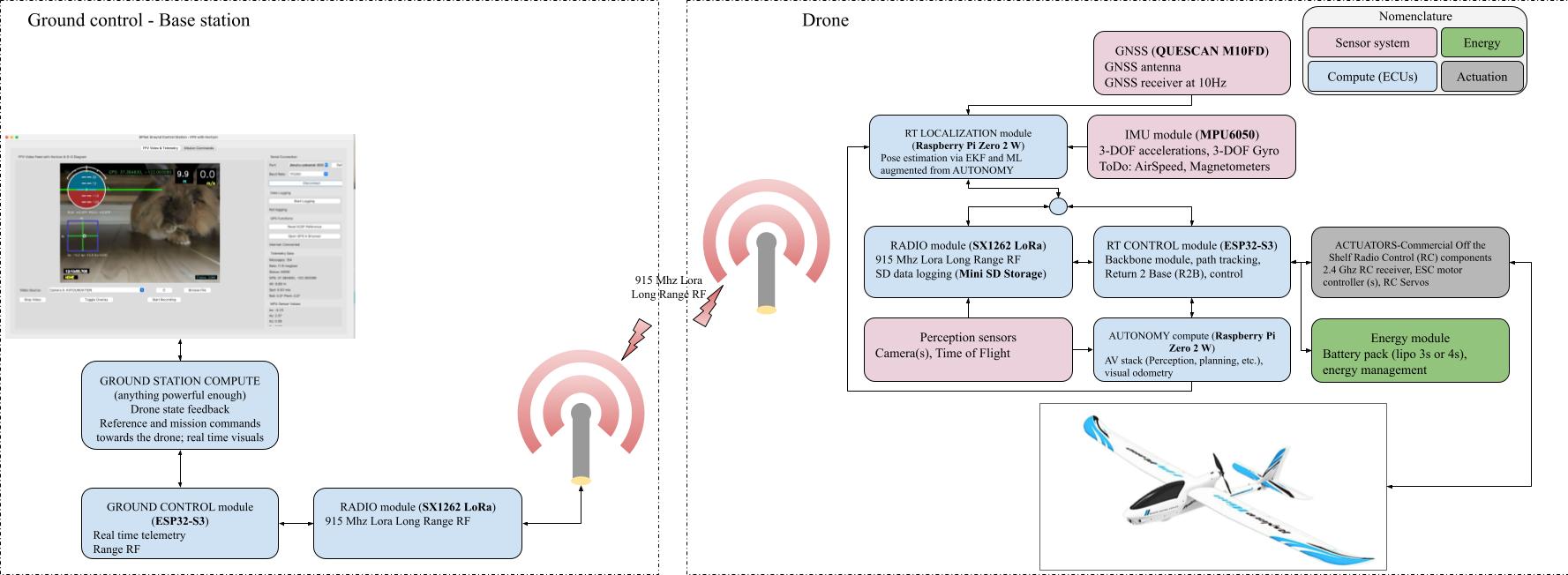
Complete System Architecture
Ground control, telemetry and drone system overview
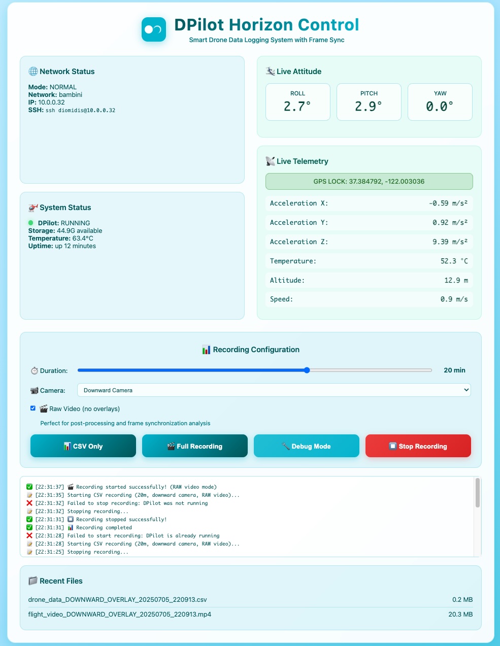
Web Interface Dashboard
Live telemetry dashboard with smartphone-accessible controls and artificial horizon
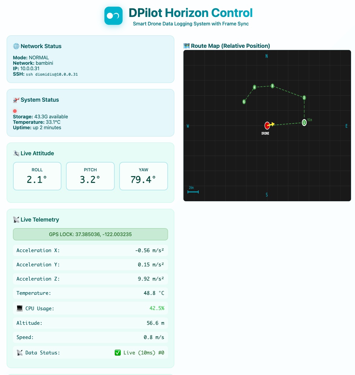
Interactive Map Interface
Web-based mission planning with real-time waypoint tracking and visualization
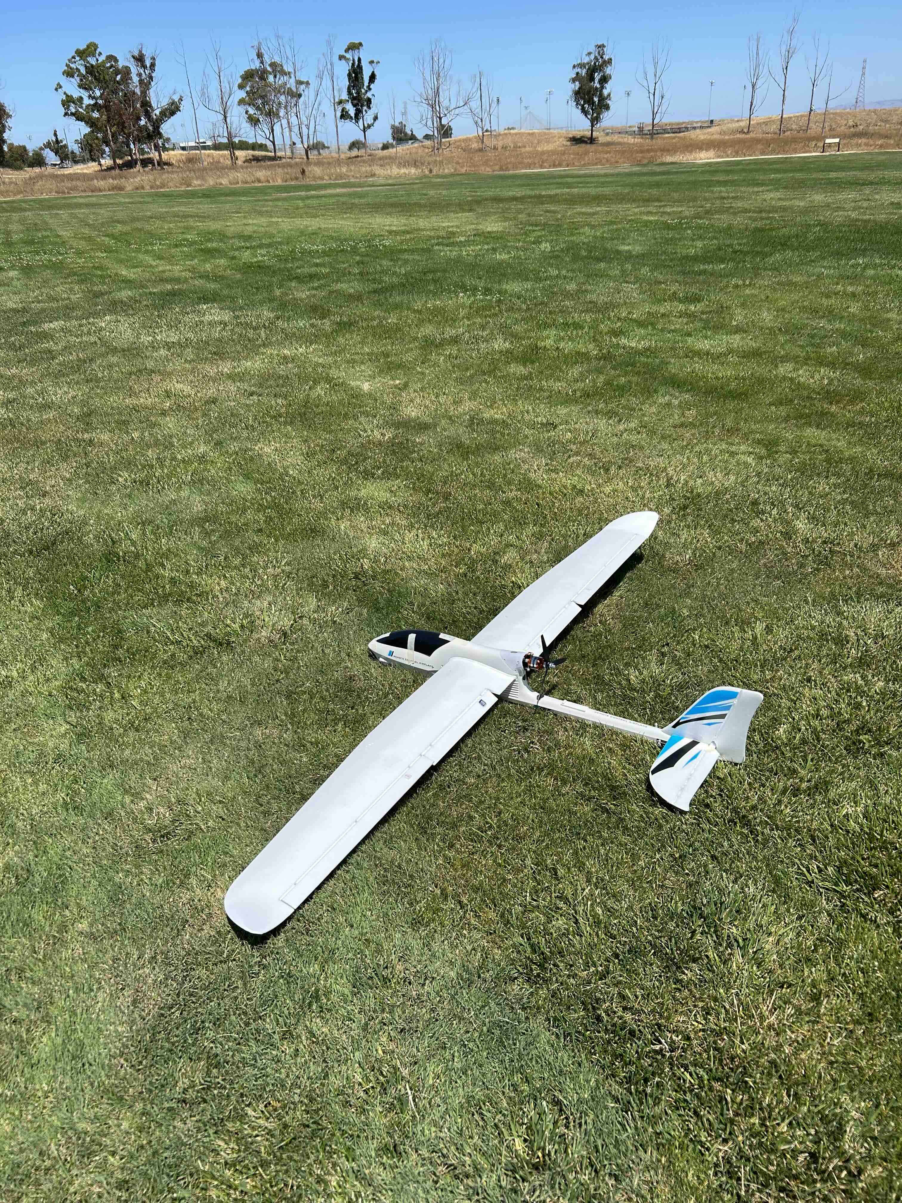
Aircraft Integration
VolantexRC Ranger with 3D printed components and visual odometry camera
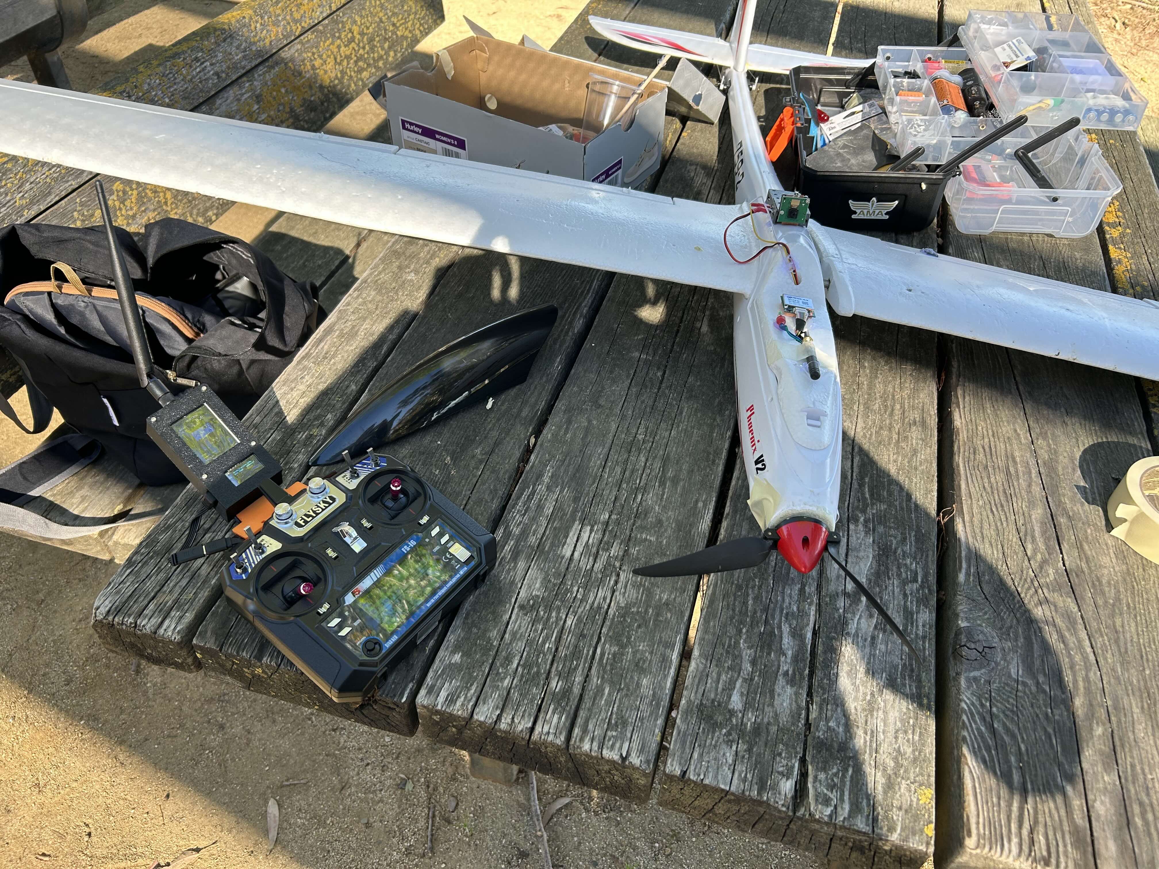
Volantex Phoenix Platform
Volantex Phoenix 2000mm with dpilot system integration
System Features
🎥 Enhanced Video Logging
- Hardware H.264 encoding with frame-perfect sync
- Custom SyncLoggerOutput (<1ms timestamp accuracy)
- 60fps high-quality recording with telemetry
- CSV logging synchronized to video epochs
- Sony IMX500 AI Camera support (12MP)
- Visual odometry processing capability
📡 FHSS Communication System
- Tenths of channel adaptive frequency hopping (902.5-927 MHz)
- Base-commanded scheduling with penalty tracking
- Asymmetric scanning
- Configurable timeout with automatic reacquisition
- AES-128 encryption on all LoRa transmissions
- Interference mitigation and penalty control
🤖 Complete Autonomous Stack
- 4-layer architecture: Route → Plan → Control → Actuate
- Motion Control control with vehicle-specific algorithms
- Smart waypoint advancement (pass-through detection)
- Mission management with circular looping
- Real-time position and velocity tracking
✈️ Mixed Mode SAFE Stabilization
- Computer guidance with P/I/D stabilization (UAV)
- UAV/UGV differentiation via elevator validity
- Shared control with pilot inputs
- Adaptive authority blending for smooth transitions
- Level flight assist and rate damping
- Conditional stabilization preserves UGV control
🛰️ Advanced Sensor Fusion
- 6-DOF pose estimation with Extended Kalman Filter
- IMU preintegration for GPS-denied navigation
- Complementary filter (0.01° roll/pitch)
- QMC5883L magnetometer (0.1° azimuth)
- DGPS provisions for a (2-5m → 0.5-1.5m accuracy)
- 50Hz time-controlled sampling with anti-aliasing
🎯 Ground Control
- Interactive map-based mission planning
- Unified state telemetry stream
- Vehicle configuration (UAV/UGV/USV)
- Live mission control with distance tracking
- H.264 video recording with flight instruments
- Multi-platform Python (Windows/macOS/Linux)
Technical Specifications
🧠 Kalman Filter Attitude Estimation
DPilot employs a sophisticated 5-state Kalman filter for high-precision attitude estimation, fusing accelerometer and gyroscope data to deliver robust roll and pitch measurements even during dynamic flight conditions.
Filter Architecture
- State Vector: [roll, pitch, roll_rate, pitch_rate, yaw_rate]
- Update Rate: 50Hz with non-uniform time handling
- Gyro Integration: Dynamic time-step adjustment
- Bias Correction: Calibrated yaw rate bias removal
- Noise Models: Tuned process and measurement covariances
Innovation Analysis
- Real-time Monitoring: Innovation factor visualization
- Statistical Analysis: Means and standard deviations
- Performance Target: <2° steady-state accuracy
- Convergence: Rapid filter stabilization (<1s)
- Robustness Target: Maintains accuracy during dynamic flying
The filter employs a two-step prediction-correction approach, first integrating gyroscope data for rapid attitude updates, then using accelerometer measurements to correct drift. The innovation factor (difference between predicted and measured values) provides real-time insight into filter performance and convergence.
This implementation handles gyroscope bias, non-uniform sampling times, and maintains high accuracy during aggressive maneuvers by carefully tuning the process and measurement noise covariance matrices.
Complete Hardware Integration
🛩️ Aircraft Platform
Main Aircraft
- Model: VolantexRC Ranger 1600/2000
- Wingspan: 1600mm/2000mm EPO foam
- Configuration: Pusher, PNP ready
- Weight: 1500-1700g with telemetry (depending on Battery)
- 🔗 Source Link
Propulsion System
- Motor: D3536 Brushless 1450KV
- Propeller: 8x6 3-blade pusher
- ESC: 60A with 4A UBEC
- Mount: Custom 3D printed
- 🔗 Motor Link
Wing Configuration
- Standard: Ranger 1600 wings
- Slow Flight: Ranger 2000 wings
- Flaps: Servo-controlled (2000)
- Sensors: Wing loading monitoring
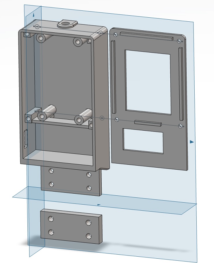
🖥️ Computing & Vision System
Mission Computer
- CPU: Raspberry Pi Zero 2 W
- RAM: 512MB LPDDR2
- Storage: 32GB+ microSD
- Housing: Custom 3D printed bucket
- 🔗 Source Link
Camera System
- Standard: OV5647 5MP Sensor
- Resolution: 1080p @ 30fps
- Upgrade: AI Camera with IMX500 (optional)
- Mounting: Downward + 15° forward
- 🔗 Source Link
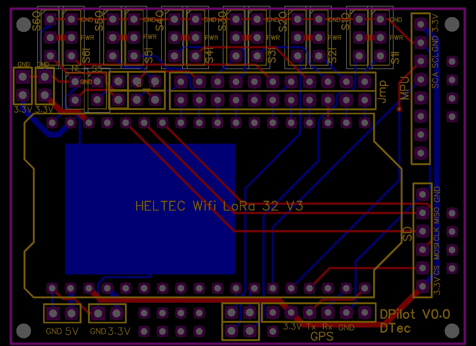
Custom PCB Module
- Design: 2-layer JLCPCB
- Controller: ESP32-S3 + SX1262
- Sensors: MPU6050 IMU integrated
- Storage: SD card module
📡 Communication & Display
Heltec WiFi LoRa 32 V3 (Drone & Ground)
- MCU: ESP32-S3 dual-core
- LoRa: SX1262 @ 915MHz
- Display: 0.96" OLED 128x64
- Power: USB-C powered
- Range: 2-5km line of sight
- Encryption: AES-128 security
- 🔗 Official Documentation
⚡ Power & Storage System
Power Regulation
- Converter: LM2596 DC-DC Buck
- Output: 5V regulated @ 3A
- Input: ESC UBEC 5V @ 4A
- Efficiency: >85% typical
- 🔗 Source Link
Data Storage
- Module: Micro SD card breakout
- Interface: SPI with pins
- Capacity: 32GB+ Class 10
- Integration: On custom PCB
- 🔗 Source Link
Power Budget
- Pi Zero 2W: 4W peak with AI camera
- Custom PCB: 2W with LoRa TX
- Total Aircraft: ~7.5W continuous
- Flight Time: >2 hours endurance
System Architecture & Data Flow
Complete System Integration
Custom PCB Integration (JLCPCB)
PCB Specifications
- Manufacturer: JLCPCB Professional
- Layers: 2-layer cost-effective
- Size: ~50x40mm aircraft fit
- Finish: HASL/ENIG RoHS
- Components: ESP32-S3, SX1262, MPU6050
Integration Benefits
- Professional manufacturing quality
- Reduced wiring complexity
- Optimized RF performance
- Integrated sensor fusion
- 3D printed environmental protection
Aircraft Mounting Strategy
Aircraft Platform Specifications
| Parameter | Ranger 1600 | Ranger 2000 | Notes |
|---|---|---|---|
| Wingspan | 1600mm | 2000mm | EPO foam construction |
| Length | 1075mm | 1075mm | Pusher configuration |
| Wing Area | 26.5dm² | 32.8dm² | High aspect ratio |
| Flying Weight | 1200-1500g | 1200-1500g | With telemetry system |
| Speed Range | Normal operations | Slow flight capable | Visual odometry optimized |
| Flap Control | None | Servo-controlled | Enhanced landing approach |
System Testing & Performance
Verified Performance Metrics
Communication Performance
- Unified State Rate: 50Hz ±1Hz sustained
- LoRa Success Rate: >95% at operational range
- Command Latency: <100ms typical
- Range Testing: >2km line of sight verified
- Encryption Overhead: <5ms per packet
Data Quality Metrics
- GPS Update Rate: 10Hz after configuration
- IMU Data Quality: <3% duplicate rate
- Video Synchronization: Frame-perfect CSV alignment
- Power Efficiency: >2 hour flight endurance
- Temperature Stability: MPU6050 calibrated
Testing Progression
Ground Testing
- Power system verification
- LoRa communication range test
- Sensor calibration and alignment
- 50Hz unified state verification
- AI camera and visual processing
- Web interface functionality
- Command response testing
Flight Testing
- Taxi tests with sensor validation
- Range tests at operational distance
- Short flights with basic telemetry
- Extended flights for endurance
- Visual odometry validation
- Mission command following
- Autonomous flight capabilities
Data Analysis
- Telemetry data quality analysis
- Video-CSV synchronization check
- Visual odometry accuracy assessment
- Power consumption optimization
- Communication reliability metrics
- System performance profiling
- Research data validation
Technical Documentation
📚 Complete Documentation
System architecture, PCB files, 3D models, and implementation guide
🔧 PCB Design Files
Professional PCB design files ready for JLCPCB manufacturing
🖨️ 3D Print Files
Custom buckets, mounts, and environmental protection components
💻 Source Code
ESP32 firmware, Python ground control, and web interface code
Ground Control Station
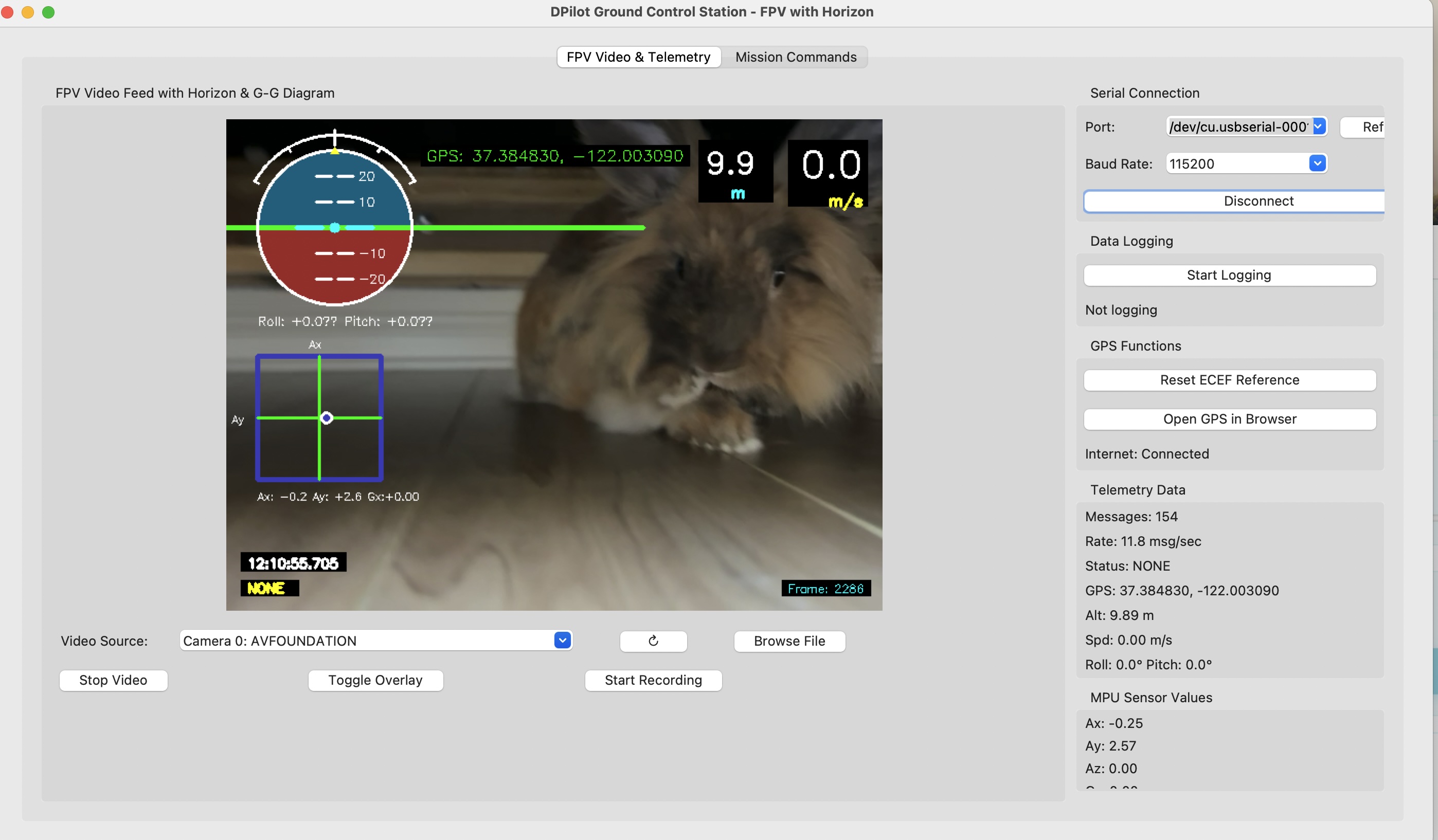
Desktop Ground Control
Python application with FPV video overlay
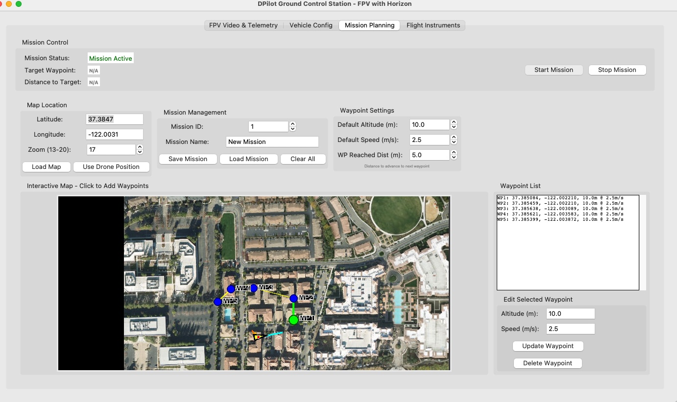
Mission Planning Interface
Interactive map-based waypoint planning with OpenStreetMap integration
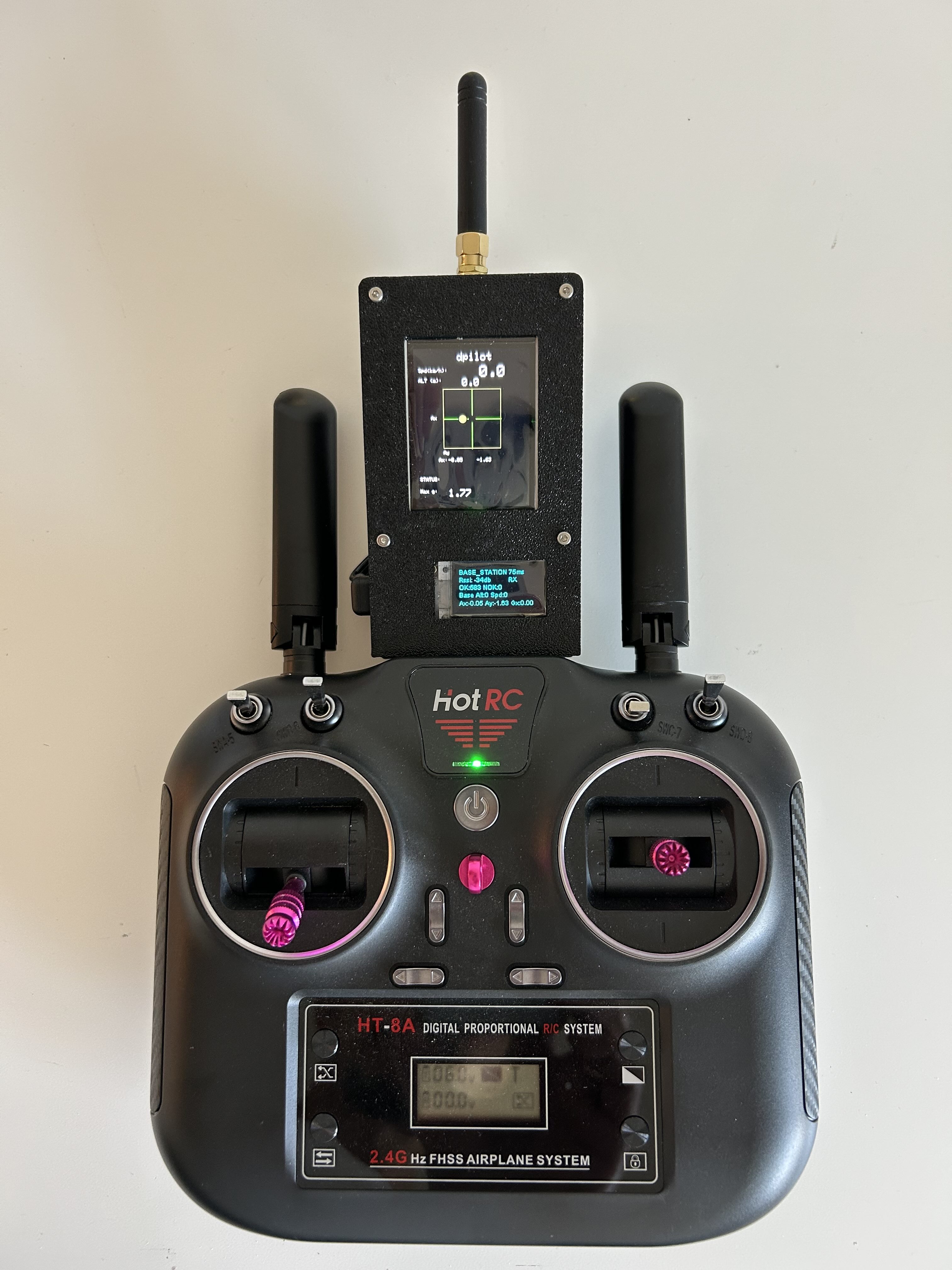
TFT Base Station Display
2" TFT with real-time G-G diagrams
Manufacturing & Assembly Process
Custom PCB Design
Professional 2-layer PCB with integrated ESP32, LoRa, IMU, and SD card
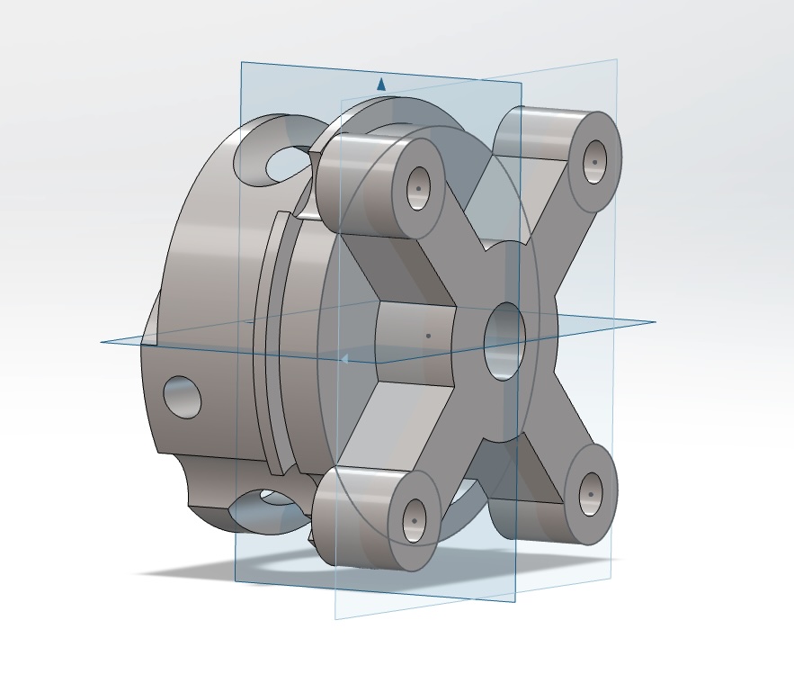
Motor mount
Custom component printing in PETG
Ground Control TFTs Displays
Custom component printing in PETG
Research Applications & Future Development
🔬 Current Research Focus
- Visual odometry algorithm development
- AI-powered feature detection and matching
- Real-time SLAM implementation
- Multi-sensor fusion techniques
- Autonomous navigation strategies
🎯 Future Capabilities
- Full autonomous flight missions
- Object detection and avoidance
- Landing site detection and selection
- Swarm coordination protocols
- Advanced AI model deployment
📊 Data Applications
- Flight dynamics research
- Aerodynamic performance analysis
- Wing loading studies
- Visual navigation validation
- Autonomous systems development
Development Roadmap
Hardware Interface Documentation
🏗️ System Architecture Overview
├── I²C Bus 1: MPU6050 IMU (SDA=47, SCL=48)
Drone ESP32 (Heltec WiFi LoRa 32 V3)
├── I²C Bus 1: MPU6050 IMU (SDA=47, SCL=48)
├── I²C Bus 2: OLED Display (SDA_OLED, SCL_OLED)
├── SPI Bus 1: LoRa Module (Built-in)
├── SPI Bus 2: SD Card (CS=26, MOSI=42, SCLK=46, MISO=45)
├── Serial 1: USB Serial (115200 baud)
├── Serial 2: GPS Module (RX=19, TX=20, 115200 baud)
└── ADC: Analog inputs (A0-A6)
Base Station ESP32 (Heltec WiFi LoRa 32 V3)
├── I²C Bus 1: OLED Display (SDA_OLED, SCL_OLED)
├── SPI Bus 1: LoRa Module (Built-in)
├── SPI Bus 2: TFT Display (CS=26, DC=45, SCLK=46, MOSI=42)
└── Serial 1: USB Serial (115200 baud)
🎯 Automatic Role Detection
System automatically determines role based on MPU6050 presence:MPU6050 Detected → Drone Mode (sensor collection, SD logging)
No MPU6050 → Base Station Mode (command relay, TFT display)
📡 Complete Pin Assignment Tables
🚁 Drone Configuration DRONE MODE
| Component | Interface | ESP32 Pins | Configuration |
|---|---|---|---|
| MPU6050 IMU | I²C Bus 1 (Wire1) | SDA=47, SCL=48 | ±8g accel, ±500°/s gyro, 10Hz filter |
| GPS Module | Serial2 | RX=19, TX=20 | 38400 baud, 8N1 |
| SD Card | SPI Bus 2 (spi1) | CS=26, MOSI=42, SCLK=46, MISO=45 | Time-controlled logging, auto file management |
| Analog Sensors | ADC | A0(12), A1(13), A2(14), A3(15), A4(16), A5(17), A6(18) | 7-channel 8-bit ADC, 0-255 range |
| Logging Button | Digital Input | GPIO 41 (Pull-up) | Single-button start/stop logging |
| OLED Display | I²C Bus 2 | SDA_OLED, SCL_OLED | 128x64 status display |
| LoRa Module | SPI Bus 1 (Built-in) | Integrated | 915MHz, 21dBm, SF7, BW=500kHz, AES-128 |
| USB Serial | Serial (Built-in) | USB Port | 115200 baud, unified state packets (50Hz) |
📡 Base Station Configuration BASE STATION
| Component | Interface | ESP32 Pins | Configuration |
|---|---|---|---|
| TFT Display | SPI Bus 2 (spiTFT) | CS=26, DC=45, SCLK=46, MOSI=42 | 240x320 ST7789, G-G diagram, flight instruments |
| OLED Display | I²C Bus 1 | SDA_OLED, SCL_OLED | 128x64 system status |
| LoRa Module | SPI Bus 1 (Built-in) | Integrated | 915MHz, 21dBm, SF7, BW=500kHz, AES-128 |
| USB Serial | Serial (Built-in) | USB Port | 115200 baud, binary command interface |